| 8. Grounding Fault Protector for BT Feeding Circuits | |||||||
|
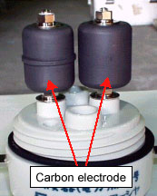
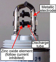
In the BT feeding circuits of AC sections on conventional lines, a grounding fault protector is connected between the negative feeding line and the overhead earth wire for flashover. This prevents the rise of voltage to ground in structures such as poles in the station yard when a trolley wire line-to-ground fault occurs, and reliably detects incidents in substations (Fig.1). In recent years, however, there has been an increase in incidents in which a protector discharges and burns during normal feeding. Investigation showed that protector discharge occurred due to voltage surges during normal feeding, and the protector was burnt by the arc heat of the AC discharge current (follow current) generated. Although discharges caused by voltage surges are normal, the follow current during discharge is one of the disadvantages of the single-gap conventional protector (Fig.3). A new type of protector with a function to inhibit the follow current was therefore developed. As shown in Fig. 2 and 4, the new protector is composed in the structure where two discharge sections in which the ceramic discharge tube (discharge start voltage: AC2500V) and the zinc oxide element (operation start voltage: AC1800V) are connected in series and sandwiched in parallel between the metallic electrodes. Field tests verified that the new protector inhibits the follow current and the protector is prevented from burning. The new protector is currently under trial use on commercial lines, and practical application is expected.  Fig.1 Schematic diagram of the overhead earth wire for flashover
|