|
For commercialization of the ground power storage device using an electrical double-layer capacitor, the RTRI has verified the device for voltage drop compensation in a 600V section and for regenerative power absorption in a 750V section.
The ground power storage device is composed of an electrical double-layer capacitor (the storage medium), a step-up/step-down chopper for power conversion and a resistor to adjust capacitor voltage. The capacitor is able to continuously charge and discharge power for 10 seconds or more at 500kW.
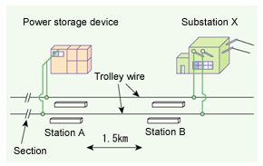
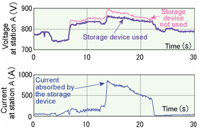
A 750V power storage device was installed in a section at the station A terminal. At this location, the feeding voltage tends to fluctuate when a train stops or starts at station A (Fig. 1). The RTRI therefore used the step-up/step-down chopper to charge the power storage device at 825V or more when a train brakes to stop at station A. A test showed that a large current (about 800A) flowed when the regenerative brake was applied (Fig. 2), verifying that the regenerative power was absorbed as designed. At the same time, the increase in the feeding voltage at station A was suppressed to about 30V, as power was charged to or discharged from the power storage device.
To confirm the insulation characteristics and DC circuit protection function of the power storage device, the RTRI also verified its charge/discharge characteristics at the 1,500V feeding circuit in its compound. Based on the test results, the RTRI proposed some essential items in using the ground storage device for the 1,500V DC system (the mainstream on DC electric railways). These included backup measures when an adjacent substation has failed, suppression of high harmonic currents and parameter setting to judge the failure of relevant circuits.
This study was promoted with a subsidy from the Ministry of Land, Infrastructure and Transport.

Fig. 1 Verification test location | 
Fig. 2 Absorption of regenerative power |
HOME > Major Results of Research and Development in Fiscal 2004 > IV Harmonization with the environment

RTRI HOME
Copyright(c) 2005 Railway Technical Research Institute,Tokyo Japan, All rights reserved.
|

