3. Techniques to estimate the vibration characteristics of structural members
- RTRI established a technique for estimating the vibration characteristics of structural members up to 200 Hz using train excitation.
- It also drew up a quick-reference chart to simplify estimation of member vibration characteristics and check for resonance.
Efforts to increase Shinkansen train speed and develop new types of structure require more insight into resonance caused by the vibration characteristics of structural members and evaluation of structural noise or ground vibration in the surrounding environment. Accordingly, the RTRI established a technique for estimating the vibration characteristics of viaduct members subjected to train excitation and evaluated vibration characteristics up to 200 Hz targeting structures such as standard rigid-frame viaducts and standard girder-type viaducts.
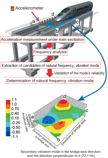
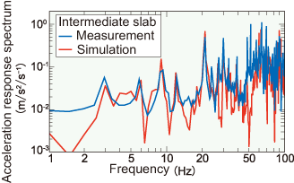
In this technique, on the basis of vibration acceleration measurements taken as trains passed a series of ‘candidate’ members with a natural frequency and vibration mode were singled out. The natural frequency and vibration modes of those members which statistically turned out to be the most reliable, were then selected(Fig. 1). This technique was used together with FEM member vibration simulation enabling more detailed investigation of member vibration characteristics (Fig. 2).
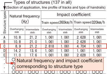
The abovementioned technique and vibration simulation of members were applied to various types of structure (137 in all), and a quick-reference chart was drawn up to allow estimation of the vibration characteristics (natural frequencies, etc.) of each member and simplify checking for possible resonance (Fig. 3).
These achievements can be utilized for purposes such as evaluating serviceability and safety against member resonance and estimating structural noise and ground vibration.
 Fig. 1 Technique to estimate member vibration characteristics and an example of estimation for the vibration mode of an intermediate slab
 Fig. 2 Comparison between measurement and vibration simulation of members using FEM
 Fig. 3 Outline of the quick-reference chart