4. A linear rail brake prototype
- RTRI produced a prototype linear rail brake and confirmed that a braking force of up to 6 kN and a reduction effect on rail heat generation of 20 to 50% can be achieved with a roller rig testing machine.
- It also developed an inverter control system capable of braking even in the event of feeder circuit failure.
Applying linear motor technology to eddy current rail brakes reduces rail heat generation (a known problem with conventional rail brakes) and creates an operation system that can be used even in abnormal situations such as feeder circuit failures. RTRI integrated the results of past research into the design/manufacture of a full-scale linear rail brake for testing with rollers and evaluated its performance (Fig. 1).
The results confirmed that a braking force of up to 6 kN (target: match the conventional type value of 5 kN) can be achieved (Fig. 2), and that the roller temperature rise is lowered by 20 to 50%, depending on section speed, compared with the conventional eddy current rail brake.
In addition, to allow continued operation of the linear rail brake even during feeder circuit failures, RTRI developed an inverter control system that starts up the inverter using the battery for the auxiliary circuit before self-generating the electric power needed for brake operation and controls the generated power and braking power at the same time (Fig. 3). Testing confirmed that the system can be started by the auxiliary circuit (battery) at 50 to 300 km/h and that predetermined braking can be implemented (Fig. 4).
It was thus confirmed that the development represents a completely independent brake with an operating source such as a power supply in addition to offering function and performance as a non-adhesive brake in contrast to the operation of other brake types.
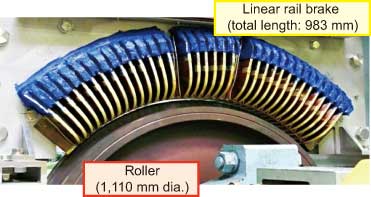 Fig. 1 Linear rail brake prototype
 Fig. 2 Test result (braking force)
 Fig. 3 Circuit configuration capable of operation even during feeder circuit failures (example of battery use for auxiliary circuit)
 Fig. 4 Start-up by the auxiliary circuit (battery) and braking test involving self-power generation
- HOME > Major Results of Research and Development in Fiscal 2009 > V Basic Research
-

RTRI HOME - Copyright(c) 2011 Railway Technical Research Institute