10. Method for analysing the mechanical performance of switch-and-lock systems
- An analysis model was developed and validated as a practical and accurate tool for estimating throwing load without field testing.
- Switching load can be estimated from the first stages in design, providing a means for more efficient product development.
The switch-and-lock systems used in turnouts comprise components such as an electric switching machine, rods, escapement cranks and switch adjusters (fig 1) . The operation of a switch-and-lock system relies on the electric switching machine supplying the appropriate switching force which in turn provides the necessary load to switch movable rails. The switching load does not only depend on rails and base plates frictional forces alone it is also influenced by the switch-and-lock system and turnout equipment itself. As such, today, other than measuring actual equipment, there is no other way to quantify the switching load.
Therefore, a method was designed to carry out modelled analyses of the mechanical performance of a switch-and-lock system. In order to calculate the power transmission and movement of each component, this model represents the various components making up the switch-and-lock: equipment, spring, attenuator, and their contact or distance as an element (Fig 2). This approach was applied to switch-and-lock systems for large turnouts to simulate switching action. The method was validated as a tool able to yield accurate estimation of the switching load and start position of the switching movement required for design (Fig 3).
This model provides an accurate estimation of switching loads. As a result, switch-and-lock systems, which previously relied heavily on extensive testing, can be developed more efficiently, and the number of prototype tests can be reduced. The proposed model is suitable for application to ordinary turnout switch-and-lock systems on high speed and conventional lines.
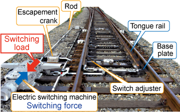 Fig. 1 Switch-and-lock system and switching load
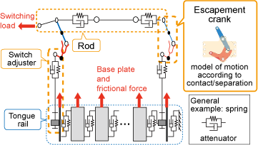 Fig. 2 Model analysis of mechanical functions
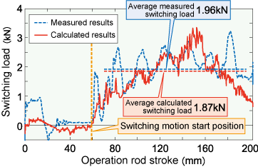 Fig. 3 Comparison between results obtained from testing and actual measurements
- HOME > Major Results of Research and Development in Fiscal 2010 > I Safety/Reliability
-

RTRI HOME - Copyright(c) 2012 Railway Technical Research Institute