4. Method for optimising control of energy storage systems
- A new control method for energy storage systems was developed to be able to operate during both the regenerating and powering modes of electric rolling stock.
- Continuous charging/discharging was simulated to validate the method.
- The control characteristics were confirmed by using an energy storage system with electric double-layer capacitors.
Fixed energy storage systems have limited capacity. As a result, if there is a lapse in the charge status of the medium, the charge/discharge process can no longer be carried out depending on the driving status (Powering/Regenerating) of the electric rolling stock (Fig 1 right).
A new control method was therefore developed which ensures that sufficient power is constantly transferred to meet the energy need of electric rolling stock, while the storage device is kept in a partial state of charge, ready for the next phase of powering or regenerating (Fig 1 left). This approach does not increase the storage capacity, but rather prevents regeneration power lapses and voltage drops in contact lines, by increasing the number of charge/discharge cycles, which in turn is expected to increase the energy efficiency of the storage system. This control method may be applied to existing energy storage systems thanks to improvements made to the control system software.
Confirmation was obtained through power simulation that the energy storage system applying the new control method could supply and absorb energy continuously (Fig 2). A prototype storage system was then built using electric double-layer capacitors (chosen for their long life cycle and expected suitability to being maintained in a partial state of charge) (Table 1, Fig 3). Trials were performed using RTRI test lines and electric rolling stock , and it was confirmed that the energy storage system could charge or discharge when the electric rolling stock was both in powering/regenerating mode.
The outcome of tests demonstrated that the control method could harness more regenerative energy compared to the former design, resulting in an improvement in energy efficiency of approximately 5%.
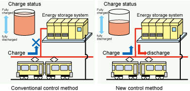 Fig. 1 Schematic diagram of the energy storage control method
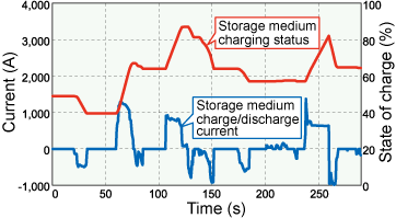 Fig. 2 Simulation results
- Table. 1 Specifications of energy storage system
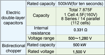
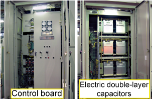 Fig. 3 Appearance of energy storage system
- HOME > Major Results of Research and Development in Fiscal 2010 > II Harmonization with the Environment
-

RTRI HOME - Copyright(c) 2012 Railway Technical Research Institute