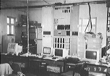
Ground equipment | 
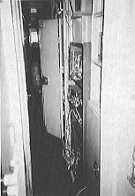
Cab equipment |

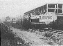
SS8 type electric locomotive | 
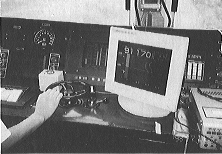
Cab display |
Collaborative tests for a digital Automatic Train Protection (ATP) for high-speed railways in China have been executed jointly by the Railway Technical Research Institute (RTRI), signalling manufacturers in Japan and the China Academy of Railway Science (CARS) for two years since 1996. This digital ATP, based on a developing system for Shinkansen in Japan, is modified as a system for high-speed railways in China. Six track circuits were installed on a 9km-long loop track of CARS and a cab receiver and a brake controller were equipped on an SS8 type electric locomotive. Tests were carried out three times from Aug. 1997 to Sep. 1998.
Characteristics of a digital ATP for high-speed railways in China
Track circuits are used for train detection in the digital ATP. The information to the cab uses digital codes and is sent by track circuits. The information is not on "speed" but on "distance". In the cab, data of gradients, speed limits on curves and points, brake performance and so on are stored. Brake patterns are calculated using these data and the information from the ground. The digital ATP is operated efficiently by a one-step brake pattern.
In the digital ATP in China, 2km-long noninsulated track circuits are used without condensers. These track circuits are stably operated to a maximum leakage conductance of 0.5 S/km. The distance between two signal houses is a maximum 40km. Carrier frequencies are 425 and 475Hz for ATP, and 525, 625, 575 and 675Hz for train detection. Length of digital codes is about 50 bits including a flag and cyclic redundancy check (CRC), and transmission speed is 25bps.
Tests on the loop track in CARS
On the loop track in CARS, five 800 to 2000m-long noninsulated track circuits and a 500m-long insulated track circuit were installed. The latter was simulated as a track circuit at a station. The shunt current of a receiving end of a track circuit was almost 1A and train shunt sensitivity was larger than 0.3ohm in every track circuit.
In performance tests by the SS8 type locomotive, we measured the difference between the location displayed in the cab and the actual location on the ground, and executed brake performance by a one-step brake pattern. We also measured frame error rates of digital codes from ground to cab including the case where noise of traction current overlaid on the signal. We also measured brake performance when the cab or ground equipment malfunctioned or digital codes from ground were not received. We were able to obtain necessary data from the tests successfully which were implemented.

Ground equipment | 
Cab equipment |

SS8 type electric locomotive | 
Cab display |