6. Method for improving the efficiency of integrated logic design of safety signalling equipment
- A database was proposed for the integrated logic design of safety signalling equipment.
- Based on the proposed database, a method was put forward to make integrated logic design of level crossings and ATS systems more efficient.
- Insight was gained into how to create automatic schemas of level crossing circuit diagrams and a connectivity simulation tool.
There are many types of railway safety signalling equipment, such as interlocking equipment, level crossing control equipment and ATS, which are all linked together. Nevertheless, these pieces of equipment differ both in nature and in location and therefore require individual design.
Logic design of signalling equipment is labour intensive and therefore research was carried out to find a more efficient approach to this work. An model geared to support logic design of interlocking systems (interlocking diagrams) already exists, and this model was used experimentally as a platform to build a new general method to facilitate more efficient logic design.
The diagram below is a flow chart illustrating the structure and processes involved in the proposed system. Although the construction of interlocking, level crossing or ATS-P system diagrams may differ, they have in common the functions for constructing their track chart and route data and also require reference to other control diagrams; based on this, a database was defined for common integrated signal logic. Fundamental train operation data required for producing ATS-P and level crossing control diagrams was added to the interlocking database (block length, aspect system, gradient, etc.). Using the interlocking diagram in reference makes level crossing or ATS-P control diagram building more efficient. The possibility of automated circuit diagram generation for level crossings was confirmed by applying the general principles already used for automatically producing interlocking circuit diagrams. A possible way to design a connection simulator for testing the operational state of equipment was identified, based on the automatically generated circuit diagrams.
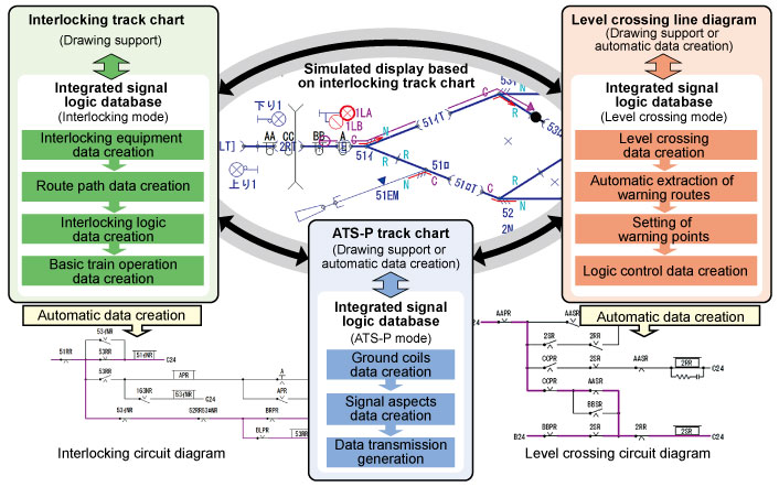
Fig.1 Structure of proposed system and flow chart showing process
- Research and Development > Major Results of Research and Development in Fiscal 2012 > III Cost Reduction
-

RTRI HOME - Copyright(c) 2013 Railway Technical Research Institute