19. Harmonics analysis modelling and harmonics suppression method for AC feeding systems
On AC feeding systems voltage or current harmonic resonance occurs within particular frequency ranges. Measures have been put in place to prevent current harmonic resonance in lower frequency ranges up to several hundred Hz in order to prevent inductive interference with communications lines. However, with the introduction of pulse width modulation (PWM) controlled vehicles, resonance is occurring in the frequency ranges of several thousand Hz, which is emerging as a new source of influence in the electromagnetic environment.
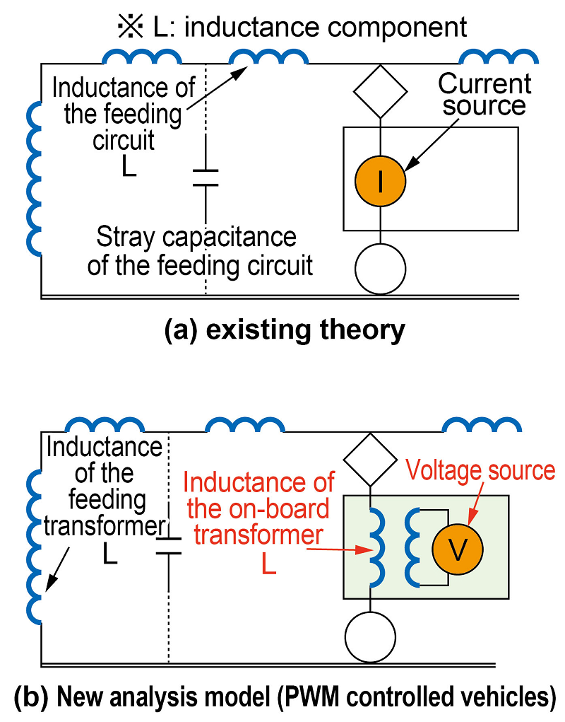
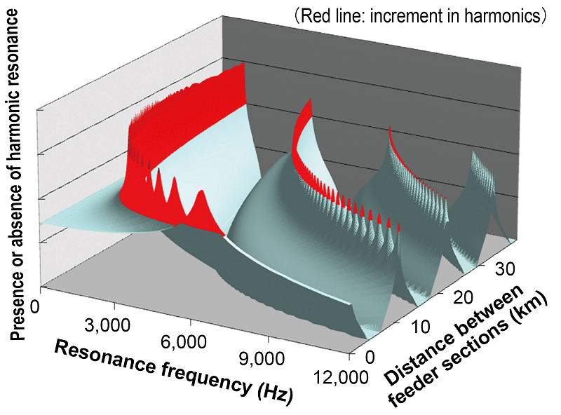
A new harmonics analysis model has therefore been proposed to evaluate the harmonics produced by PWM controlled vehicles (Fig. 1). Results from on-site tests to verify the applicability of this new analysis model confirmed that the resonance frequency value obtained through the model corresponded to the measured frequency to within a 4% margin of error. Based on the new model, the conditions giving rise to harmonic resonance in a feeding system, such as the position of the vehicle in the feeding system, and the distance between feeder sections, were evaluated quantitatively. Results also provided quantitative clarification of where resonance would occur in the case of large distances (several tens of kilometres) between feeder sections, in several frequency ranges (Fig. 2). The insight gained from this work can be applied to establish resonance control measures on new rolling stock when introduced into service.
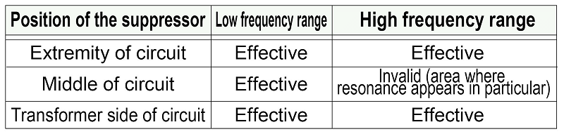
In addition, this method confirmed that the harmonics resonance suppressor currently used and located at the extremities of feeding systems would be just as effective for voltage harmonic resonance – with the exception of a few areas where resonance occurs – placed anywhere on the feeding system (Table 1).