19. Voltage control method for DC electric traction system with variable inductor
Optimized control of feeding voltage supplying DC electrified railway lines should generate energy savings and result in higher efficiency of power supply.
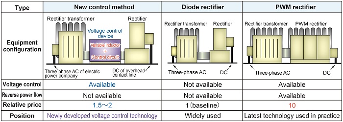
Robust and inexpensive diode rectifiers (middle of Table 1) widely used today cannot control their output voltage, and although the newest PWM rectifiers (right side of Table 1) that are able to control voltage are being used in practice as well, they are approximately ten times more expensive than diode rectifiers.
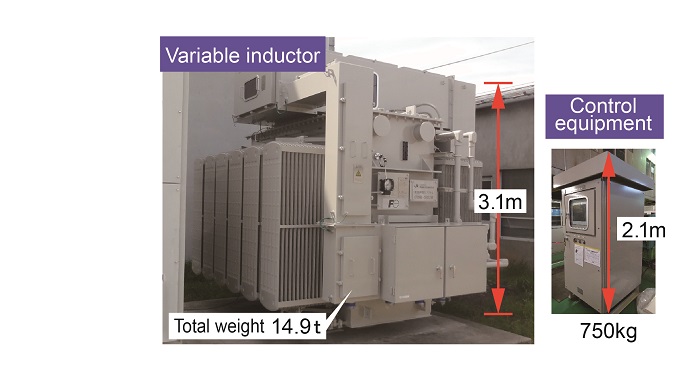
Consequently, a new voltage control method has been designed (left side of Table 1), composed of a voltage control device built with a voltage control circuit and a variable inductor (Fig. 1) connected to a rectifier transformer with a rectifier installed on both sides. This variable inductor type method is based on a technology patented by the Tohoku Electric Power Co., Inc. The equipment configuration and design method were then adapted for use on the railways. Contrary to PWM rectifiers, the new method has some constraints, for example it does not allow reverse power flow (so regenerated power cannot be reused as a power source in stations etc.), however, it can reduce costs to approximately 20% of the latest existing method (about 1.5 to 2 times the cost of diode rectifier).
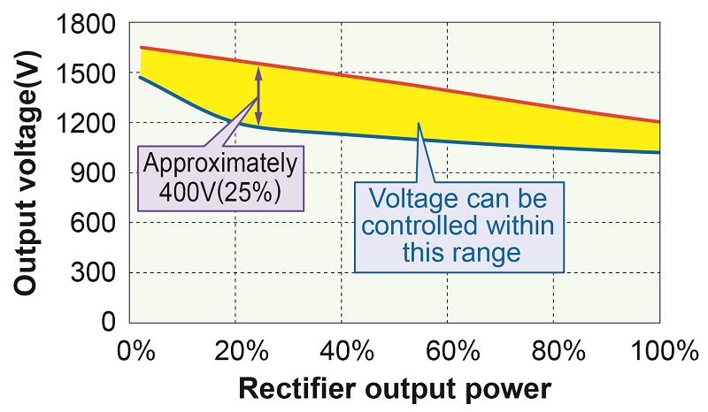
A prototype with a small capacity of rated current (500A) was built (Fig. 1), to validate the function and effectiveness of the new method. Results confirmed that the rated voltage (1500V) could be controlled to approximately within a maximum of 25% (approx. 400V) (Fig. 2). ICT is used to exchange data in real time between rolling stock and substations, which should allow energy savings to be made across the whole DC railway network. The new method can also be used as a measure against voltage drops in the DC electric traction system.