18. Device to determine fouling of structural clearance gauge using on-board 3D laser scanner
To guarantee the running safety of railway vehicles, it is essential to determine whether any trackside structures foul the clearance gauge.
In the past this was achieved manually or with a specially equipped car for inspecting the structural clearance gauge, however, the problem with this method, is that it is both time and labor intensive, and the initial cost of building such special cars is expensive.
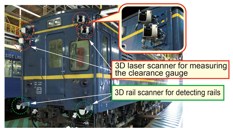
Consequently, using a “3D laser scanner” which measures distances to target objects based on beam reflection time, a clearance gauge fouling detection device was developed, which can measure trackside installations continuously (Fig. 1). The device can be mounted on any kind of vehicle, and can inspect structural clearance gauges at up to 80km/h, making it possible to check the structural clearance gauges at a lower cost.
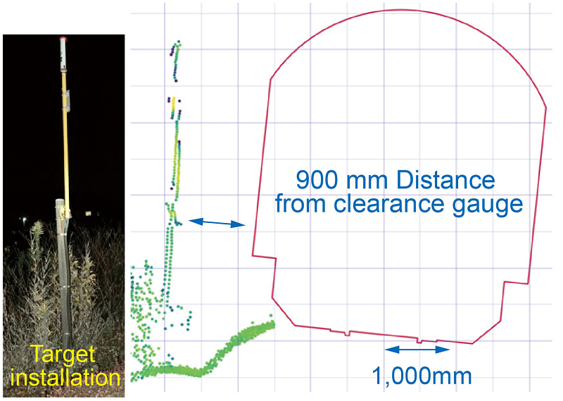
In order to measure the clearance gauge, two pairs of 3D scanners are fitted to the top left and right gable ends of the front of a vehicle. Two more 3D scanners are mounted on each side of the lower part of the front end of the vehicle to measure the track position, to correct vehicle vibration when running. The lateral error in distance measured for larger trackside installations, such as level crossing gates and equipment boxes was within 50 mm, while for thinner items, such as signaling markers, the error margin was within 200mm, confirming that the system satisfied the target accuracy (within 200mm) (Fig. 2).
Satisfying the accuracy criterion of 200 mm, signifies that depending on the conditions of the track section, the need for manual measurement could be kept to below 10%.
Given that this device is fitted onto a track geometry inspection car, the structural clearance can be measured according to the schedule of usual track geometry inspections.
Consequently, the clearance gauge can be checked now without the need for a specially operated car.
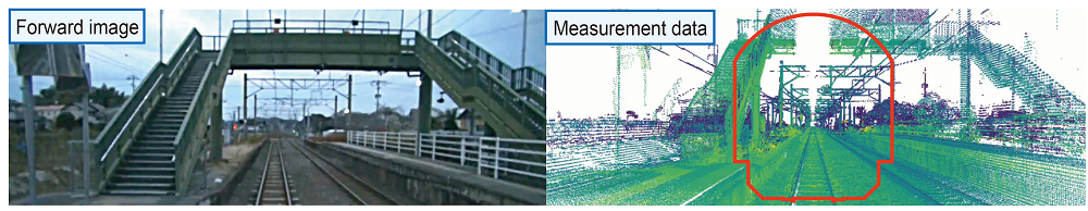
In addition, given that the data is collected in 3D configuration (Fig. 3), it is possible to identify which piece of an installation is fouling the gauge, and obtain the cross-sectional shape of the track bed, to determine how good or bad a situation is.
Other Contents
- 12. Method for monitoring state of driving devices using vibration analysis and machine learning
- 13. Wheel flange-wear reducing wheel-tread friction block
- 14. High-strength bolted friction joints for existing weathering steel bridges
- 15. Bridge pier stability monitoring method using microtremor data
- 16. Low-cost continuous welded rail track structure suitable for regional railways
- 17. Track stiffness inspection method using portable track stiffness measuring device (RFWD)
- 18. Device to determine fouling of structural clearance gauge using on-board 3D laser scanner