9. Design Method for Post-installed Anchor Joint Members in the Reconstruction of Concrete Structures
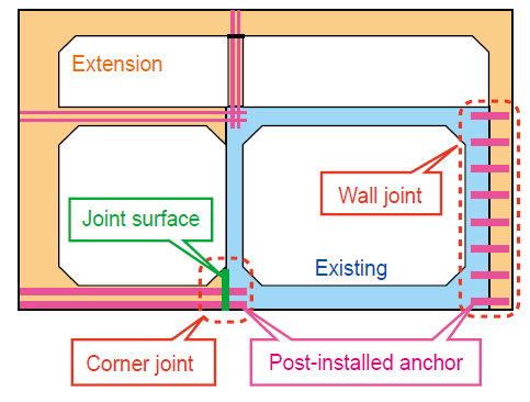
To improve convenience at stations and other areas, there has been an increasing number of cases where additional members are installed on existing cut and cover tunnels and rigid-frame viaducts using the post-installed anchor method (Figure 1). However, a rational design method for member joints has not been proposed, and considering it from the safety measures side, cases of using an excessive number of anchors can be frequently seen. In such cases, it has sometimes been difficult to perform anchor installation and ensure quality in existing structures with overcrowded reinforcements.
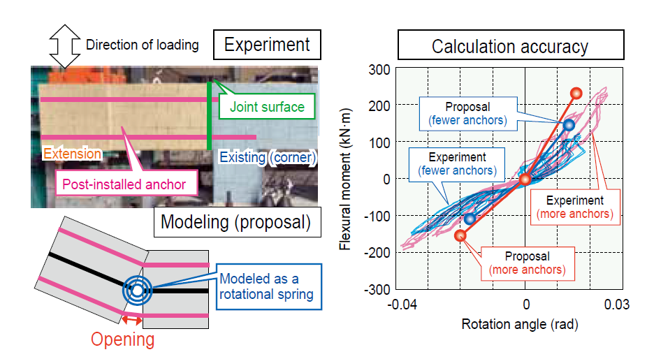
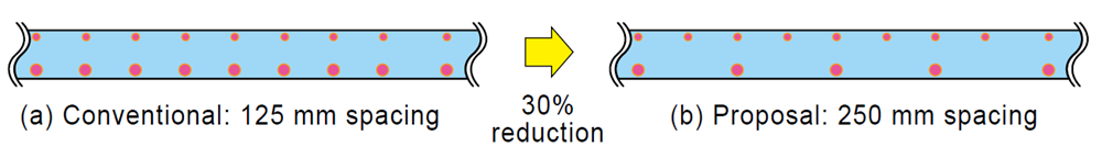
To address this, a design method was developed that accounts for the type of joint members, the quantity and positions of anchors, and the roughening of the joint surface. For corner joints, a method was proposed in which the opening of the joint surface caused by the pullout of anchors from corner is modeled as a rotational spring, and the stiffness of the joint member is calculated based on the quantity and positions of the anchors (Figure 2). For wall joints, a shear capacity calculation method was proposed that considers the effects of friction and interlocking of aggregates at the joint surface. Trial calculations for cut and cover tunnels showed that the amount of post-installed anchors could be reduced by approximately 30% for both beam-to-column connection joints and wall joints (Figure 3).
These design methods are reflected in the guidelines for post-installed anchors and can be applied in the reconstruction of concrete structures. This design method enables rational structural planning and selection of joint members, allowing for greater design flexibility in accommodating various structural forms and spatial requirements.
Other Contents
- 9. Design Method for Post-installed Anchor Joint Members in the Reconstruction of Concrete Structures
- 10. Reinforcement Method for Preventing Fatigue Cracks at Steel Girder Support Sections
- 11. Method for Identifying Potentially Critical Locations of Loose Bearing Based on On-board-measured Track Geometry
- 12. Extension of Rail Replacement Cycles Considering Fatigue/Soundness
- 13. Support Method for Extending Inspection Periods Based on Statistical Analysis of Equipment Inspection Records
- 14. Automated Visual Inspection System for Vehicle Underbody
- 15. Autonomous Train Operation System
- 16. General Purpose Real-time Algorithm for Generating Driving Curves for Driver Advisory System
- 17. Method for Updating On-board Databases Using Public Communication Networks
- 18. Labor-saving for Generating Crew Schedule to Enable Workforce Efficiency and Reduce Labor Burden