22.Verification of High Temperature Superconducting Flywheel Storage Systems
Flywheel Energy Storage Systems work by having an in-built flywheel (rotor), which changes the electric power to kinetic energy which is then stored, and can release electric power on demand by reconverting the kinetic energy back into electricity.
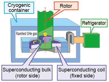
The specificity of the flywheel energy storage system being verified in this paper is that it uses high-temperature superconducting magnetic bearings. The system has a high-temperature superconducting bulk body rotating shaft and high-temperature superconducting bearings, which produces a step-change improvement in supporting force and means that the bearing can be made relatively much smaller than before for the load it must support (Fig. 1).
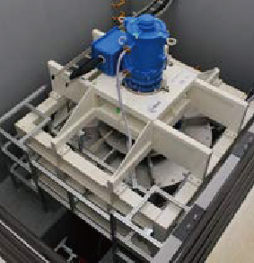
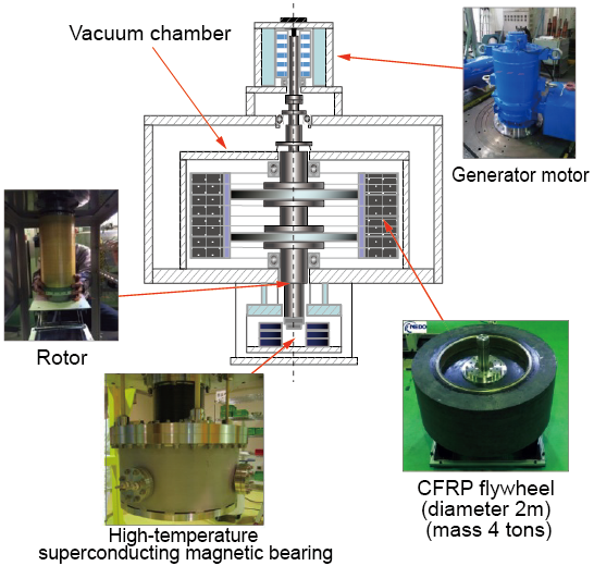
The demonstration machine used for verification tests (Figs. 2 and 3) had a 2 m diameter and a mass of 4 tons, supported by a CFRP superconducting magnetic-bearing flywheel. Rotations were adjusted through the generator motor; therefore, it was possible to test the system’s capacity to absorb and release 300 kW of power, and verify it could store 25kWh of power.
The superconducting magnetic bearing was cooled with a commercially available compact cooler, removing the need for liquid nitrogen etc., and electric power consumption was less than 1% of output power. Since September 2015 this demonstration machine has been used in verification tests to equalize solar photovoltaic power output (at the Yamanashi prefecture facility).
This storage system, apart from the fact that it does not suffer wear from repeated charging and discharging, is low-loss, long-life and low-maintenance and is suited for use on the railways for regenerative power purposes and as a measure to prevent voltage dropping. The next step will be to design the energy storage system for use on the railways.