11. Multi-point synchronous measurement system for railway bridge vibration using a video camera
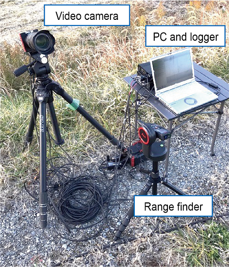
In order to improve the efficiency and sophistication of inspections using vibration measurement, which can evaluate the dynamic characteristics of structures with objective numerical data, we have developed a multi-point synchronized vibration measurement system using a 4K video camera capable of high-speed imaging (Fig. 1), and applied it to the inspection of railway bridges. The displacement of a railway bridge caused by a running train is calculated from the amount of change in the video image and the ratio of the sizes between the actual size and the image of the object being photographed. With this method, it is possible to measure vibrations at multiple arbitrary points in the captured image synchronously by simply shooting a video without setting up a target on the object being measured.
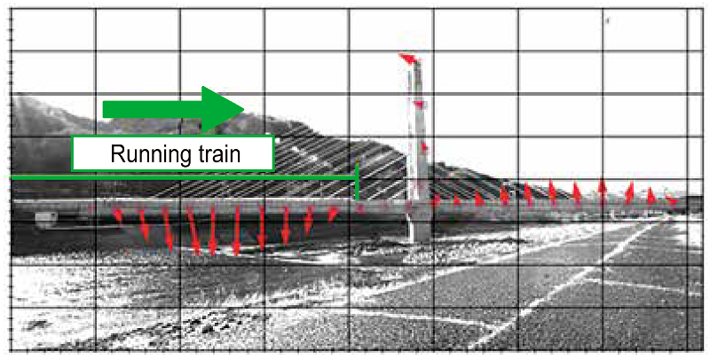
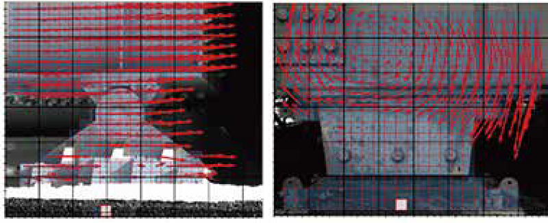
If the camera is shaken by wind, etc. during shooting, an error is caused. However, the proposed method automatically finds immovable points in the image such as bridge abutments that do not move even when a train passes by, and corrects the error caused by the vibration of camera by determining the relative vibration between the immovable points and the point to be measured. In addition, the displacement by vibration can be obtained in actual amplitude by determining the relationship between the gap and the actual size at any point in the image based on the result of simple measurement using the attached range finder. By shooting a video of the railway bridge when a train passes by from a riverbank, etc., the dynamic deflection and vibration shapes of the railway bridge can be measured (Fig. 2), and the deflection angle and bending moment of the bridge can be estimated from the differentiation of the deflection. It can also efficiently measure multiple posts for overhead contact lines, etc. at once. Moreover, it can measure horizontal, vertical, and rotational displacements of the bearing with an accuracy of less than 0.1 mm and 0.1 degrees, respectively, which is difficult to measure visually (Fig. 3). Periodical measurements will help to find the deformation of bearings, such as damage and movable parts sticking. In this way, this system can achieve sophisticated labor-saving inspections.
Other Contents
- 9. Restoration techniques for embankments reusing collapsed soil
- 10. Structural performance evaluation of existing bridges by acceleration monitoring
- 11. Multi-point synchronous measurement system for railway bridge vibration using a video camera
- 12. Low-cost deterioration evaluation method for the backside ground of slope protection works
- 13. Boring method for constructing a crossing structure under railway tracks making it possible to shorten the construction period
- 14. Maintenance method for prestressed concrete sleepers according to the installation environment
- 15. Low-cost ballastless tracks for existing lines and roadbed improvement method
- 16. The image analysis engine for around track to support train patrol
- 17. Insulator contamination estimation method based on public data
- 18. Degradation evaluation method for lithium-ion batteries for vehicle control circuits