15. Improving OCL connector fatigue resistance
Connectors that form an electrical link between contact wires and messenger wires are subject to fatigue damage from the vibrations caused by passing pantographs and so far, no effective solution has been proposed to tackle this problem. As such a set of anti-fatigue design guidelines, and a prototype connector based on these recommendations, were developed.
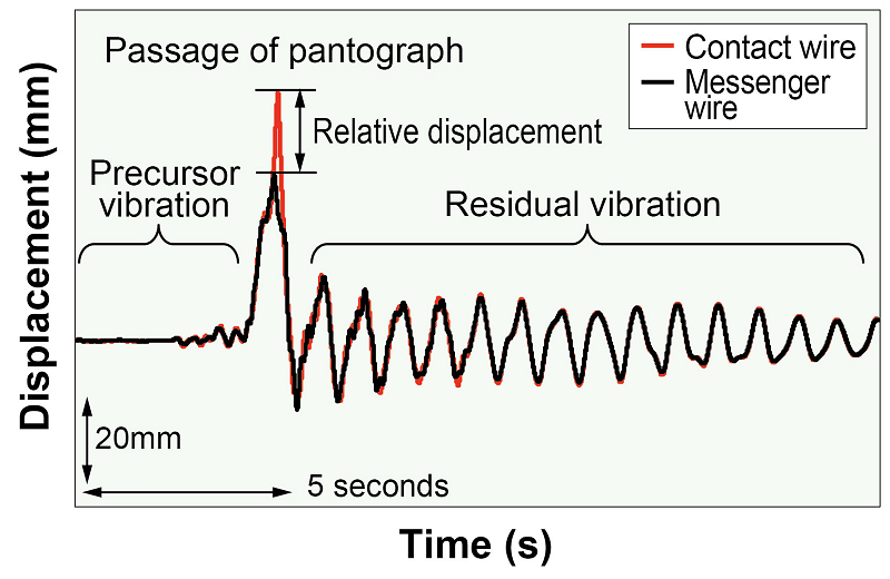
The main source of fatigue damage on connectors is the relative displacement between contact wires and messenger wires (Fig.1). Furthermore, the damage is particularly stark when resonance occurs between the connectors. Analyses of OCL vibrations on conventional lines, found that the maximum relative displacement was 40mm, whilst the frequency of precursory and residual vibrations was situated in the 0.8-8.0Hz range. These results were taken as the new criteria for fatigue evaluation.
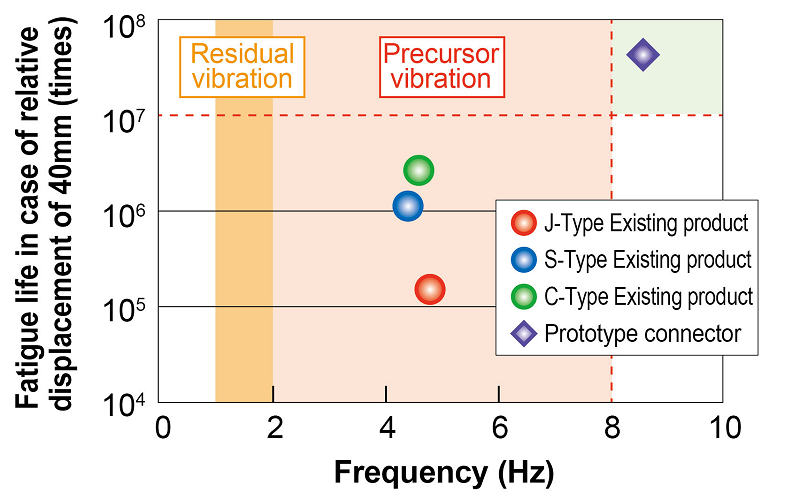
The natural frequency of the connectors and the fatigue life corresponding to the relative displacement of 40mm were obtained using finite element analysis, which in turn was applied to determine fatigue resistance (Fig. 2). The proposed anti-fatigue design guidelines recommended a fatigue life in excess of 10 million applications of stress for a relative displacement of 40mm, and the natural frequency of the connector equalled or exceeded 8.0Hz, which is above the precursor and residual vibration frequency range.
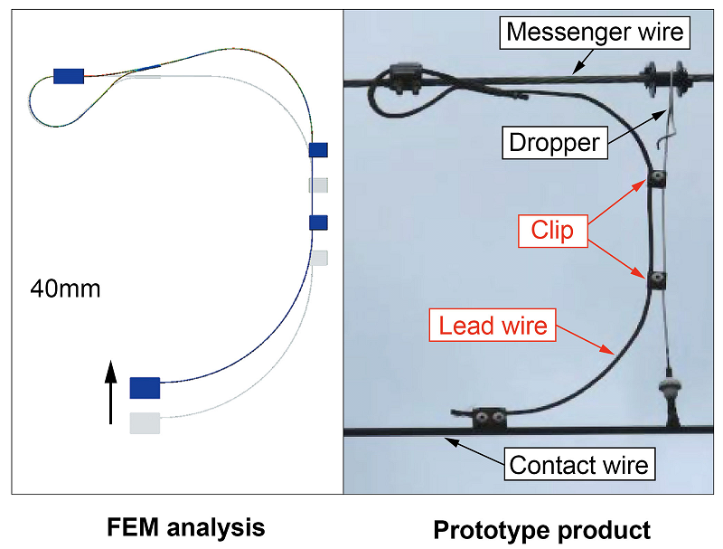
The prototype connector shown in Fig. 3 was designed using FEM analysis. Confirmation was obtained that the fatigue life corresponding to the given relative displacement 40mm and resonance was equal to or over 10 million applications of stress. During a six-month trial using the prototype connector on a conventional line there were no cases of ruptured lead wires and it was confirmed that there was no increase in wear on the contact wire.
Other Contents
- 10. Design method for concrete filled tube members with rectangular section
- 11. Tunnel lining crack detection method using deep learning or multi-layer neural network
- 12. Methods to detect and predict rapid localized deterioration of track irregularity
- 13. Development of new solid-bed track with resilient sleepers using shear-key to achieve efficient construction work
- 14. Profiling (through grinding) of aging rails based on X-ray diffraction analyses
- 15. Improving OCL connector fatigue resistance
- 16. Proposal for light weight high-rigidity car body structure
- 17. Reduction in manufacturing cost of C/C composite pantograph contact strips and clarification of their wear limit
- 18. Method for evaluating serviceable life and deterioration of electronic interlocking equipment